Create cross sections
Displaying a cross section of a 3D model is like cutting it in half and looking inside. Use the Cross Section Controls dialog box to adjust the alignment, offset, and tilt of the cutting plane.
- Click the Toggle Cross Section icon
 on
the 3D toolbar to turn on or off the cross section.
on
the 3D toolbar to turn on or off the cross section. - (Optional) Click the arrow next to the Toggle Cross Section
icon, and choose Cross Section Properties, which opens the Cross
Section Controls dialog box. Then do any of the following:
-
Change settings under Alignment, Display Settings, and Position and Orientation.
-
Click the Save Section View button to save the current cross-sectional view. (The saved view will appear on the Views menus in the 3D toolbar and Model Tree with a default name, SectionView[n].)
-
 Cross Section Controls options
Changes you make here are applied immediately in the PDF. To see these changes, make sure that the Cross Section Controls window does not block your view of the active 3D model. The Cross Section Controls window remains on top if you focus or interact with the underlying PDF. To close it, click the Close button in the upper right corner.
- Enable Cross Section
-
When selected, makes the other options available.
- Alignment
-
Determines the axis (x, y, or z) to which the cross section aligns. Clicking Align To Face and then clicking a surface area (face) of the 3D object—it is not necessary to close the dialog box first —cuts the cross section along the plane defined by that surface.
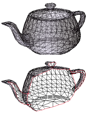
- Show Intersections
-
Indicates where the cutting plane slices the 3D model by adding a colored outline. Click the color swatch if you want to select a different color.
- Show Cutting Plane
-
Displays the two-dimensional field that cuts the 3D model. Click the color swatch if you want to select a different color, and enter a different percentage if you want to change the opacity of the plane.
- Align Camera With Cutting Plane
-
Rotates the 3D model so that it’s level with the cross section’s cutting plane.
- Offset
-
Determines how much of the 3D model is sliced. Drag the slider left or right.
 To understand how each axis
divides the 3D model, select an axis and then drag the Offset slider
back and forth and observe the changes in the embedded 3D model.
To understand how each axis
divides the 3D model, select an axis and then drag the Offset slider
back and forth and observe the changes in the embedded 3D model. - Flip
-
Reverses the cross section. For example, if the top half of the model is cut off in the cross section, clicking Flip displays the top half and cuts off the bottom half.
- Tilt sliders
-
Determine the angles between the cutting plane and the axes. Drag the sliders left or right, or change the percentages.
- Save Section View
-
Adds the current cross-sectional view to the lists in the 3D toolbar and Model Tree, where you can select it to return the model to this view. The saved view is given a default name, SectionView[n].