Tutorial 40: Drawing in OpenGL using jit.gl.sketch
The OpenGL capabilities of Jitter provide us with a variety of tools for creating animated scenes in three dimensions. The Jitter OpenGL objects we’ve looked at thus far each perform a fairly straightforward task, be it creating simple geometries (jit.gl.gridshape and jit.gl.plato), importing OBJ models (jit.gl.model), or manipulating the position of objects and scenes (jit.gl.handle). More complex scenes can be built by using several of these objects at once. After a certain point, however, it may make sense to work with an object that understands OpenGL commands directly and can be used to perform a large number of drawing commands at once. This object is jit.gl.sketch, and it is the subject of this Tutorial.
The jit.gl.sketch object interfaces with the OpenGL system in Jitter just as other OpenGL objects; as a result, it may help to review Tutorial 30: Drawing 3D Text and Tutorial 31: Rendering Destinations before we begin. In addition, the messages and attributes understood by jit.gl.sketch bear a strong resemblance to the methods and properties of the JavaScript sketch object used in the Max jsui object. Designing User Interfaces will give you some additional information on the capabilities of OpenGL vector graphics that is common to both of these systems.
The majority of the messages used by jit.gl.sketch are slightly modified versions of standard functions within the OpenGL API. The entire API is outside the scope of this Tutorial; however, the standard reference for these functions (the OpenGL “Redbook”) is available online at:
Converting between OpenGL code as given in the “Redbook” and elsewhere (in the C programming language) and messages to jit.gl.sketch is reasonably straightforward if the following conventions are kept in mind:
All OpenGL commands are lowercase in jit.gl.sketch. Thus the OpenGL function glColor() becomes the Max message glcolor sent to jit.gl.sketch.OpenGL symbolic constants, in addition to being lowercase, lose their “GL_” prefix, so that GL_CLIP_PLANE1 (in OpenGL) becomes clip_plane1 when used with jit.gl.sketch, for example.
In addition to the basic OpenGL API, jit.gl.sketch also understands a number of high-level drawing commands to instruct the object to render basic shapes and perform vector graphics-style drawing operations.
Open the tutorial patch.
The Tutorial patch consists of a series of Jitter objects used for rendering in OpenGL: a jit.gl.render object, a jit.pwindow object, and a jit.gl.sketch object. The jit.gl.sketch object is sent messages from a bpatcher object containing message box objects containing lists of commands. Different views of the bpatcher can be obtained by selecting different offsets from the umenu object connected to it. In this Tutorial we'll step through the different sections of the bpatcher one-by-one and look at the messages contained in each view.
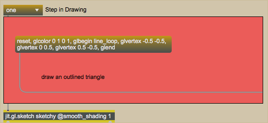
Our jit.gl.sketch object receiving messages from within a bpatcher.Click on the toggle box labeled Display attached to the qmetro object at the top-left of the patcher.
By starting the qmetro object, we’ve begun rendering our OpenGL scene. Our jit.gl.render object shares it’s name (sketchy) with the jit.pwindow object and the jit.gl.sketch object in the patch. Because of this, the jit.pwindow will display anything drawn by the jit.gl.render object, which in turn will draw whatever the jit.gl.sketch object instructs it to draw.
The command list
Set the umenu object attached to the bpatcher to read “one”. The bpatcher object will show a message box containing a series of messages separated by commas. Click on the message box to send its contents to our jit.gl.sketch object.
A green triangle should appear in the jit.pwindow object.
A green triangle drawn with a sequence of messages to jit.gl.sketch.
Technical Detail: The jit.gl.sketch object works by maintaining a command list of OpenGL commands that are then executed every time the scene is drawn (in our patch, when the jit.gl.render object receives a bang). Most of the messages we send to jit.gl.sketch become part of this command list. This command list can be stored in the internal memory of the object or, if the displaylist attribute of jit.gl.sketch is set to 1, it can be stored on the GPU of our computer. When working with large numbers of commands, turning on the displaylist attribute will speed up rendering time; however, new commands added onto the list may take longer to be added if they are sent very quickly, as they need to be loaded onto the GPU.
Our first message box sends the following messages in sequence to jit.gl.sketch:
The reset message to jit.gl.sketch simply tells the object to clear its command list and reinitialize itself. What follows are a sequence of OpenGL commands. The glcolor command tells jit.gl.sketch to change the color it uses to draw. As with all OpenGL objects in Jitter, these colors are floating-point values in RGBA (red, green, blue, alpha) order; thus, glcolor 0 1 0 1 tells jit.gl.sketch to draw in a fully opaque (alpha=1) green.
The glbegin message tells jit.gl.sketch to interpret what follows as instructions defining an object. The argument to glbegin specifies the drawing primitive to use when rendering the shape. The primitive we’ve chosen, line_loop, will take a set of points (called vertices) and connect them with lines, completing the shape by connecting the last vertex to the first vertex again. Thus in a shape with four points A, B, C, and D, our object will contain lines from A to B, B to C, C to D, and D to A.
The glvertex messages contain the coordinates of the points in our shape. If only two coordinates are given, they are interpreted as x and y values. If three coordinates are given, the last value is interpreted as a z coordinate. The glend message tells jit.gl.sketch that we’ve finished defining the shape. We could then move on to another shape (or execute other commands) if we so desired.
Step one of our patch therefore resets the object, sets the color to green, and instructs it to draw an outlined shape with three vertices connected to one another. These messages (with the exception of the reset message) form the command list for jit.gl.sketch for the image we see in the jit.pwindow.
More about drawing primitives
Select the umenu object and set it to “two”. Click on the message box that appears in the bpatcher. Our outlined triangle should disappear and a filled green triangle should take its place.A filled green triangle.
The list of commands in our message box is very similar to the first one:
Once again, we reset the object and then define a color (green) and an object with three vertices to be drawn. The only difference is the drawing primitive specified as an argument to the glbegin message. In this example, we’re using triangles as our drawing primitive. This tells jit.gl.sketch to interpret triplets of vertices as triangles. Rather than outlining the shape as we did before, we’ve now instructed jit.gl.sketch to generate a polygon. As a result, the interior of our vertices is filled with the specified glcolor (green).
There are ten (10) different drawing primitives recognized by OpenGL and, as a result, by objects such as jit.gl.render and jit.gl.sketch. They are points, lines, line_strip, line_loop, triangles, triangle_strip (abbreviated tri_strip), triangle_fan (abbreviated tri_fan), quads, quad_strip, and polygon. These primitives each specify the algorithm by which a series of vertices will be connected. Tutorial 37: Geometry Under the Hood and Table 2-2 and Figure 2-7 of the OpenGL “Redbook” give descriptions and examples of each and describe their common uses.
Set the umenu object in the Tutorial patch to “three” and click the message box that appears in the bpatcher. A triangle with a rainbow surface will appear in place of the solid green triangle.A shape with different colored vertices.
In this command list, we’ve embedded glcolor commands for each vertex of our triangle:
As a result, our jit.gl.sketch object sets our three vertices to red, green, and blue, respectively, and fills in the interior surface with a color gradient that fades smoothly between the three colors. The smooth_shading attribute of jit.gl.sketch allows this behavior when set to 1 (as is the case with the jit.gl.sketch object in our Tutorial patch).
Set the umenu object in the Tutorial patch to “four”. Set the umenuinside the bpatcher to “fill”. Our jit.pwindow now contains a square with a rainbow-colored surface. Set the umenu to “outline”. Now we only see rainbow-colored lines outlining the shape, as well as a diagonal across it.A square made up of connected triangles, filled and unfilled.
This section of the bpatcher allows us to see how a drawing primitive works to make a more complex shape. We begin our command list with the glpolygonmode command, which tells jit.gl.sketch whether to fill in complete polygons or leave them as outlines, exposing the skeleton that defines how the vertices are connected. The first argument to glpolygonmode defines whether we’re talking about the front of the shape, the back of the shape, or both (front_and_back, as we’re using here). The second argument defines whether that side of the shape will be filled (fill) or left outlined (line). The poly_mode attribute of the Jitter OpenGL objects accomplishes the same thing.
After we’ve reset and decided how we want our shape drawn (filled or outlined), we supply a shape description:
As with the triangle in our previous example, we provide a glcolor for each glvertex (in this example red, green, blue, and white for the four points of the square). The tri_strip drawing primitive used as an argument to glbegin tells jit.gl.sketch to draw the shape as a series of triangles where the last two vertices of a triangle are recycled into the next triangle. Thus a polygon with six vertices A, B, C, D, E, and F would be drawn as four triangles using the tri_strip primitive: ABC, CBD, CDE, and EDF (the ordering ensures that the triangles are all drawn with the same orientation). In our code, we get a shape with two triangles that when connected and filled appear to us as a square.
Rotation, translation, and scaling
Set the umenu in the Tutorial patch to “five”. Click and drag the number box in the bpatcher slowly upwards from 0 to 360. The filled rainbow square from the previous example will reappear and rotate in a counter-clockwise direction.A rotation matrix applied to an object.
In addition to defining shapes containing vertices and colors, jit.gl.sketch allows us to manipulate something called the modelview matrix so our objects can be animated and scaled. Our command list sets this up for us by supplying some additional commands:
reset,
glpushmatrix,
glrotate $1 0 0 1,
After resetting everything, we send the glpushmatrix message, which copies our current modelview matrix onto a stack, allowing us to return to it later. This allows us to create nested translations for drawing complex objects. For example, we could draw a series of polygons, each with rotations relative to the previous polygon; in this way we could generate sequences of shapes that have the same orientation with respect to each other but could then all be rotated with respect to another group of shapes. The use of a stack for this process greatly aids in modeling as we can use simple face-on coordinates for the vertices in our shapes and then tell the renderer to compute the rotations for us. The glrotate command specifies the degrees of rotation for our shape followed by three values that specify the axis of rotation as an xyz vector. Thus we’re rotating our object around the z axis (which spins the shape along the x-y plane of the screen).
Following the rotation, we continue with our command list as in the previous example. At the end of the shape specification, we complete our command list with the glpopmatrix command, which returns our jit.gl.sketch object to the previous rotation. New commands added to the command list after that would then use the original rotation vector, not the one we’ve applied to our shape.
Set the umenu to “six”, and manipulate the number box objects attached to the pak object inside the bpatcher. We can now rotate our square around all three axes. In addition, lines are rendered to provide us with unit vectors to guide us in our rotation.A rotation matrix applied to multiple objects (a square and three vectors).
Our command list here sets up a new modelview matrix and performs the rotation three times in series:
This allows us to rotate our shape along the x axis, y axis, and z axis in sequence according to the values of the number box objects in our patch. We then create four objects using this rotation before we send a glpopmatrix to return to our original orientation. After our square is rendered, we create three two-vertex lines in different colors oriented along the same axes as the plane:
The drawing primitive lines simply connects all the vertices in the shape (unlike line_loop, it does not connect the last vertex back to the first). Notice that because these objects (and our square) are all within the same modelview matrix, they all share the same rotation.
Set the umenu to “seven” and manipulate the number box objects in the bpatcher. The colored square can be moved along the x and y axes of the space.A translation matrix applied to our shape.
In addition to image rotation, the modelview matrix can apply translation of an image. This allows us to specify vertices for our object centered around (0, 0) and then move the object anywhere we want in the space. The gltranslate message in our command list performs this function, taking as arguments the x and y offsets that will be applied to every vertex in the shape(s) affected by the transformation.
Set the umenu to “eight” and manipulate the number box objects in the bpatcher. The colored square can be stretched along both axes.Our object transformed by scaling.
Just as we can rotate and translate a shape or shapes, we can also control their scaling with the glscale message. The vertices in our shape are multiplied by the arguments to the glscale message (specified as x, y, and optional z scaling factors).
The order in which you provide glrotate, gltranslate, and glscale commands to jit.gl.sketch is important, as they are processed sequentially and cumulatively to create the final transformation of the affected objects. For example, say you have a vertex at coordinates (0.5, 1). If you translate that vertex by (0.2, 0.2) and then scale it by (1.5, 1.5) the vertex will end up at (1.6, 1.7). If you reverse the order of those operations (scale then translate), your vertex will end up at (0.95, 1.7).
Summary
The jit.gl.sketch object gives us access to the powerful OpenGL API, allowing us to define and execute an OpenGL command list within a Max patch. Lists of vertices, specified by glvertex messages and bracketed by glbegin and glend messages, can be used to specify the shapes of objects. The glbegin command takes a drawing primitive as its argument that defines the algorithm by which the vertices are connected and filled. You can use the glpolygonmode command to expose the outlined structure of a shape, and you can color entire shapes or vertices using glcolor messages. You can perform rotation, translation, and scaling of a defined shape by sending the glmatrixview command with the argument modelview. Using glrotate, gltranslate, and glscale commands, you can then specify a viewing transformation. The glpushmatrix and glpopmatrix commands allow you to define a stack of these transformations so that you can change the rotation, position, and size of shapes either independently or in nested groups within a sequence of OpenGL commands.
Embed a visible subpatch inside a boxRender Open GLGL parallel to lcdIn-Patcher Window
 Our
Our 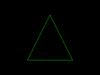 A green triangle drawn with a sequence of messages to
 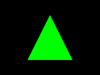 A filled green triangle.
 A shape with different colored vertices.
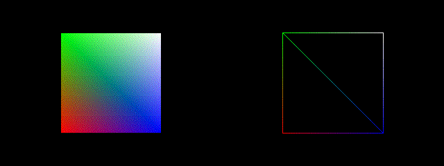 A square made up of connected triangles, filled and unfilled.
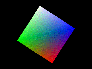 A rotation matrix applied to an object.
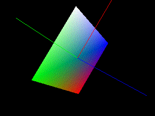 A rotation matrix applied to multiple objects (a square and three vectors).
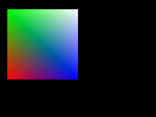 A translation matrix applied to our shape.
 Our object transformed by scaling.