3D Models
Basic Performance Setup
Jitter Tutorials
Tutorial 37: Geometry Under the Hood
This tutorial demonstrates the low-level support in Jitter to use matrices to store and manipulate geometry data and render them with the jit.gl.mesh object. Since the data is contained in an ordinary Jitter matrix, this opens up a world of possibilities where arbitrary matrix operators may be used to generate and/or process the geometry matrices. The tutorial will cover the matrixoutput attribute of the GL group, the organization of data in geometry matrices, an example of how geometry matrices can be processed using matrix operators, and introduce various drawing primitives supported by the jit.gl.mesh object.
Open the tutorial patch and click on the toggle object labeled Start Rendering.
Matrix Output
Click on the toggle box labeled Turn matrixoutput on/off.
Wait a minute—the sphere that was just there a moment ago has disappeared. What's going on?
Some of the objects in the GL group support the matrixoutput attribute, and jit.gl.gridshape is one such object. This attribute determines whether or not the object's geometry is rendered directly in the object's associated drawing context or if the object sends a matrix containing geometry data out its left outlet. The geometry is not visible because it is being sent to a gate, which is closed.
Select the menu item print from the umenu object labeled "Matrix Destination"
In the max window you should see a series of messages like "print: jit_matrix u26300000007 quad_grid". This is similar to what you've seen in previous tutorials as the output of objects, which pass matrix data, with the exception, that there is an extra element. Rather than sending the message jit_matrix [matrix-name], as you should be familiar with, the jit.gl.gridshape object sends message jit_matrix [matrix-name] [drawing-primitive]. In this case the drawing primitive is quad_grid, which means interpret the matrix as a grid of quadrilaterals.
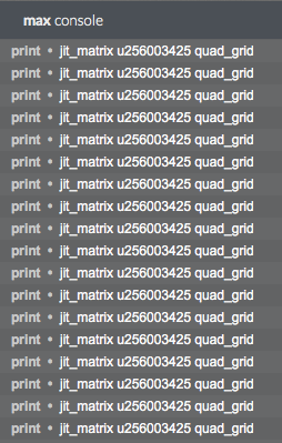 The output of the jit.gl.gridshape object in the Max Console
At the time this tutorial was written, the only objects that support the matrixoutput attribute are the jit.gl.gridshape , jit.gl.nurbs, and jit.gl.plato objects. However, by the time you read this, there may be other objects, which support this mode of operation.
There is still no excitement in our window, but this is easily remedied.
Select the menu item direct from the umenu object labeled Matrix Destination.
The sphere is now visible again, because the message jit_matrix [matrix-name] [drawing-primitive] is being sent to the jit.gl.mesh object. In response to this message, the jit.gl.mesh object draws the supplied matrix using the specified drawing primitive. If no drawing primitive is specified, the jit.gl.mesh object's current drawing primitive will be used. Valid drawing primitives are: points, lines, line_strip, line_loop, triangles, tri_strip, tri_fan, quads, quad_strip, polygon, tri_grid, and quad_grid.
The jit.gl.mesh object's current drawing primitive may be set using the @draw_mode attribute and can be set to any one of the valid drawing primitives mentioned above.
In the same fashion that you can change the dimensions of video data, you can change the dimensions of the matrix output by sending the jit.gl.gridshape object the dim message. By default the dimensions of the matrix output by the jit.gl.gridshape object is 20 by 20.
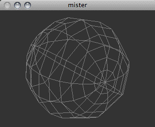
Click on the toggle box labeled Wireframe.
Change the number box labeled Matrix Dimensions.
Try rotating the wireframe sphere with the mouse
 “The Death Star plans are not in the main computer.”
You may have noticed that in this patch the jit.gl.handle object is communicating with the jit.gl.render object rather than the jit.gl.gridshape object. This has the effect of rotating and positioning the entire scene. The @inherit_transform 1 argument is necessary in order to do this correctly, otherwise the rotation would be compositied again with the scene's rotation, causing major confusion.
Geometry Matrix Details
Video in Jitter is typically represented by 4-plane char data, but how is the geometry data being represented?
Each vertex in the geometry is typically represented as float32 data with 3, 5, 8, 12, or 13 planes. Planes 0-2 specify the x, y and z position of the vertex. Planes 3 and 4 specify the texture co-ordinates s and t. Planes 5-7 specify the normal vector nx, ny and nz used to calculate the effects of lighting on the geometry. Planes 8-11 specify the red, green, blue, and alpha vertex color. Plane 12 specifies the edge flag e.
The output matrix of the jit.gl.gridshape object has 12 planes, but since we are not applying a texture to the geometry, and lighting is not enabled, the texture coordinates and normal vectors are ignored.
Processing the Geometry Matrix
Instead of simply rendering the geometry unaltered, as you've done so far, it is possible to process this geometry with matrix operators.
Select the menu item xfade from the umenu object labeled Matrix Destination.
Now the matrix is being sent through the jit.xfade object to cross fade the geometry matrix with a matrix of noise. Just as the jit.xfade object may be used to crossfade between video matrices, it may be used to crossfade between geometry matrices.
Click on the button object labeled "Generate Noise"
Gradually change the number box labeled "Crossfade Value" to 0.1.
Turn wireframe rendering on and off by clicking the toggle box labeled Wireframe. Notice how the noise deforms both the geometry and the color of the shape.
This will subtly deform the sphere with noise, as well as introduce random colors. The texture coordinates and normal vectors are also being affected, but this is not visible since there is no texture being applied, and lighting is not enabled.
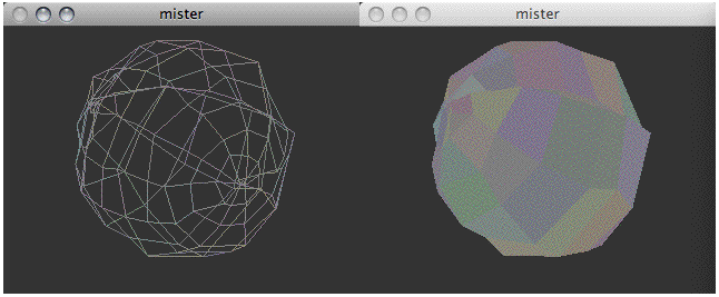 A slightly distorted sphere (wireframe and filled)
Click on the button object labeled "Generate Noise" several more times, or turn on the toggle box labeled "Rapid Noise" to generate a new matrix of noise for each time the geometry is drawn
Gradually change the number box labeled "Crossfade Value" to 1.0. Again, turn wireframe rendering on and off to see how the noise is visualized.
A slightly distorted sphere (wireframe and filled)
Click on the button object labeled "Generate Noise" several more times, or turn on the toggle box labeled "Rapid Noise" to generate a new matrix of noise for each time the geometry is drawn
Gradually change the number box labeled "Crossfade Value" to 1.0. Again, turn wireframe rendering on and off to see how the noise is visualized.
Now the geometry being drawn is pure noise.
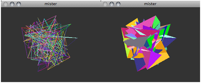 White noise expressed as a geometry (wireframe and filled)
Set the number box labeled "Crossfade Value" back to 0.
White noise expressed as a geometry (wireframe and filled)
Set the number box labeled "Crossfade Value" back to 0.
Drawing Primitives
You will notice that despite the fact that jit.gl.gridshape is outputting the message jit_matrix [matrix-name] quad_grid, we are appending the output of jit.xfade with quad_grid. This is because most matrix operators will ignore the drawing primitive argument and simply output the message jit_matrix [matrix-name]. Hence we need to append the name of the drawing primitive to the message. This provides a good opportunity to experiment with various drawing primitives.
Try selecting the various menu items available in the umenu labeled Drawing Primitive.
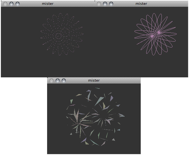 Using different drawing primitives: points (left), line_strip (center), and triangles (right)
Summary
In addition to drawing directly to their associated drawing contexts, some objects in the GL group support the matrixoutput attribute. When enabled, the geometry matrix is sent out the object's left output with the message jit_matrix [matrix-name] [drawing-primitive].
Geometry matrices are typically float32 data with a plane count of 3, 5, 8, 12, or 13 planes, and may be processed using arbitrary matrix operators in a similar fashion to processing video matrices.
The jit.gl.mesh object supports various drawing primitives via the @draw_mode attribute to render these geometry matrices: points, lines, line_strip, line_loop, triangles, tri_strip, tri_fan, quads, quad_strip, polygon, tri_grid, and quad_grid.
Generate simple geometric shapes as a connected grid
Use mouse movement to control position/rotation
Render Matrix Data as a Shape
Render Open GL
Crossfade between 2 matrices