<?xml version="1.0" encoding="utf-8" standalone="yes"?>

<?xml-stylesheet href="./_c74_tut.xsl" type="text/xsl"?>

<chapter name="MSP Synthesis Tutorial 3: Using Amplitude Modulation">
	<previous module="msp"  name="06_synthesischapter02"></previous>
	<next module="msp" name="06_synthesischapter04"></next>
	<parent name="00_mspindex">MSP Tutorials</parent>

<setdocpatch name="03yAmplitudeModulation" patch="03yAmplitudeModulation.maxpat"/>

<h1>
	Synthesis Tutorial 3: Using Amplitude Modulation
</h1>


	<h2>
		Ring modulation and amplitude modulation
	</h2>

	<p>
		Amplitude modulation (AM) involves changing the amplitude of a <i>carrier</i>
		signal using the output of another <i>modulator</i> signal. In the specific
		AM case of ring modulation (discussed in the previous tutorial) the
		two signals are simply multiplied. In the more general case, the
		modulator is used to alter the carrier's amplitude, but is not the
		sole determinant of it. To put it another way, the modulator can
		cause fluctuation of amplitude around some value other than 0. The
		example below illustrates the difference between ring modulation
		and more common amplitude modulation.
	</p>

<illustration><img  src="images/synthesischapter03a.png"/></illustration>

	<caption>
		<i> Ring modulation versus Amplitude modulation</i>
	</caption>

	<p>
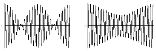
		The example on the left is 1/4 second of a 100 Hz cosine
		multiplied by a 4 Hz cosine; the amplitude of both cosines
		is 1. In the example on the right, the 4 Hz cosine has an
		amplitude of 0.25, which is used to vary the amplitude of the
		100 Hz tone ±0.25 around 0.75 (going as low as 0.5 and as high
		as 1.0). The two main differences are a) the AM example never
		goes all the way to 0, whereas the ring modulation example does,
		and b) the ring modulation is perceived as two amplitude dips
		per modulation period (thus creating a tremolo effect at twice
		the rate of the modulation) whereas the AM is perceived as a single
		cosine fluctuation per modulation period.
	</p>

<br/>

	<p>
		The two MSP patches that made these examples are shown below.
	</p>

<illustration><img  src="images/synthesischapter03b.png"/></illustration>

	<caption>
		<i> Ring modulation versus Amplitude modulation</i>
	</caption>

	<p>
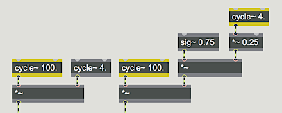
		The difference in effect is due to the constant value of <m>0.75</m>
		in the AM patch, which is varied by a modulator of lesser amplitude.
		This constant value can be thought of as the carrier's amplitude,
		which is varied by the instantaneous amplitude of the modulator. The
		amplitude still varies according to the shape of the modulator, but
		the modulator is not centered on 0.
	</p>


	<techdetail>
		<b>Technical detail: </b>The amount that a wave is offset
		from 0 is called the <i>DC offset</i>. A constant amplitude value
		such as this represents spectral energy at the frequency 0 Hz. The
		modulator in amplitude modulation has a <i>DC offset</i>, which
		distinguishes it from ring modulation.
	</techdetail>

<br/>

	<h2>
		Implementing AM in MSP
	</h2>

	<p>
		The tutorial patch is designed in such a way that the DC offset
		of the modulator is always 1 minus the amplitude of its sinusoidal
		variation. That way, the peak amplitude of the modulator is
		always 1, so the product of carrier and modulator is always 1.
		A separate <o>*~</o> object is used to control the over-all amplitude of the sound.
	</p>

	<bullet>
		Click on the <o>ezdac~</o> to turn audio on. Notice how the
		tremolo rate is the same as the frequency of the modulator.
		Click on the <o>message</o> boxes <m>2</m>, <m>4</m>, and <m>8</m>
		in turn to hear different tremolo rates.
	</bullet>

	<h2>
		Achieving different AM effects
	</h2>

	<p>
		The primary merit of AM lies in the fact that the intensity of
		its effect can be varied by changing the amplitude of the modulator.
	</p>

	<bullet>
		To hear a very slight tremolo effect, type the value 0.03 into
		the <o>number</o> box marked ‘Tremolo Depth’. The modulator
		now varies around 0.97, from 1 to 0.94, producing an amplitude
		variation of only about half a decibel. To hear an extreme tremolo
		effect, change the tremolo depth to 0.5; the modulator now varies
		from 1 to 0 - the maximum modulation possible.
	</bullet>

	<p>
		Amplitude modulation produces sidebands - additional frequencies
		not present in the carrier or the modulator - equal to the sum
		and the difference of the frequencies present in the carrier and
		modulator. The presence of a DC offset (technically energy at 0 Hz)
		in the modulator means that the carrier tone remains present in the
		output, too (which is not the case with ring modulation).
	</p>

	<bullet>
		Click on the <o>message</o> boxes containing the numbers <m>32</m>,
		<m>50</m>, <m>100</m>, and <m>150</m>, in turn. You will hear the
		carrier frequency, the modulator frequency (which is now in the
		low end of the audio range), and the sum and difference frequencies.
	</bullet>

	<p>
		When there is a harmonic relationship between the carrier and
		the modulator, the frequencies produced belong to the harmonic
		series of a common fundamental, and tend to fuse more as a
		single complex tone. For example, with a carrier frequency of
		1000 Hz and a modulator at 250 Hz, you will hear the frequencies
		250 Hz, 750 Hz, 1000 Hz, and 1250 Hz; the 1st, 3rd, 4th, and
		5th harmonics of the fundamental at 250 Hz.
	</p>

	<bullet>
		Click on the <o>message</o> boxes containing the numbers <m>200</m>,
		<m>250</m>, and <m>500</m> in turn to hear harmonic complex tones.
		Drag on the ‘Tremolo Depth’ <o>number</o> box to change the depth
		value between <m>0.</m> and <m>0.5</m>, and listen to the effect
		on the relative strength of the sidebands.
	</bullet>

	<bullet>
		Explore different possibilities by changing the values in
		the <link type="refpage" name="number">number box</link>
		objects. When you have finished, click on the <o>ezdac~</o>
		to turn audio off.
	</bullet>

	<p>
		It is worth noting that any audio signals can be used
		as the carrier and modulator tones, and in fact many
		interesting results can be obtained by amplitude modulation
		with complex tones. In a later tutorial, we'll look at how
		to perform amplitude modulation on the sound coming into
		our computer.
	</p>

<h2>Summary</h2>

	<p>
		The amplitude of an audio (carrier) signal can be
		modulated by another (modulator) signal, either by
		simple multiplication (ring modulation) or by adding
		a time-varying modulating signal to a constant signal
		(DC offset) before multiplying it with the carrier
		signal (amplitude modulation). The intensity of the
		amplitude modulation can be controlled by increasing
		or reducing the amplitude of the time-varying modulator
		relative to its DC offset. When the modulator has a DC
		offset, the carrier frequency will remain present in the
		output sound, along with sidebands at frequencies determined
		by the sum and the difference of the carrier and the
		modulator. At sub-audio modulating frequencies, amplitude
		modulation is heard as tremolo; at audio frequencies the
		carrier, modulator, and sidebands are all heard as a
		chord or as a complex tone.
	</p>

</chapter>


