In the previous tutorial, you saw how to position the camera and objects in the GL group to construct an OpenGL scene in Jitter. After understanding this tutorial, you’ll be able to hide selected polygons of an OpenGL object based on their spatial orientations, draw selected polygons in filled and wireframe modes, and add the results to the draw buffer using antialiasing and blending.
Open the tutorial patch. Click on the toggle box labeled “Start Rendering.”
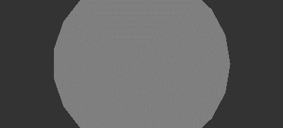
You should see a gray sphere in the jit.pwindow in the tutorial patch. It is drawn by a jit.gl.gridshape object, connected to a jit.gl.handle object that allows you to control its rotation. The jit.gl.handle object's auto_rotate attribute is on, so once you rotate it the sphere will continue to rotate along the axis you set. If you like, give it a spin.
The gray sphere.
Wireframe Mode and Culling Faces
Just below the label “OpenGL Objects to Render” in the example patch is an object pakpoly_mode 1 1. This object generates messages that set the polygon mode attribute of the jit.gl.gridshape object.
Click both toggle objects above the pak poly_mode object. You should see the gray sphere in wireframe mode.The sphere in wireframe mode.
Turning wireframe mode on allows you to see clearly that the jit.gl.gridshape object approximates a sphere using polygons -- in this case, quadrilaterals. Every polygon drawn in OpenGL has a front side, defined as the side from which its vertices appear to wrap in a clockwise direction. Each polygon in a scene can, therefore, be categorized as either front-facing or back-facing, depending on whether its front side is pointed towards or away from the camera.
OpenGL can automatically hide either front-facing or back-facing polygons, which can serve to speed up drawing greatly or highlight certain aspects of data being visualized. In Jitter, you can control polygon visibility on an object-by-object basis using the cull_face attribute.
Set the number box above the prependcull_face object to 1.The front-facing polygons of the sphere.
The cull_face attribute of a GL group object can be set to 0, 1 or 2. A setting of 0 shows all polygons in the object. A setting of 1 hides the back-facing polygons. A setting of 2 hides the front-facing polygons. With the current setting of 1, the wireframe sphere appears solid, because the hidden lines -- polygon edges that would not be visible if the sphere were made of a solid material -- are not drawn. The rotation (did you give it a spin?) convincingly depicts that of a real-world solid object.
Set the number box above the prependcull_face object to 2.The back-facing polygons of the sphere.
Now the front-facing polygons are hidden. It’s as if you are looking through the sphere and seeing only the inside part that faces towards you. You can see from this picture that the perspective is somewhat strange, but watching the rotation in the patch makes it really obvious that the scene is not drawn “normally.”
In general, setting cull_face 1 will do a good job of removing the polygons that should be hidden for solid, convex objects such as the sphere. But for objects that aren’t solid, a combination of the front-facing and back-facing polygons may be in view.
Set the number box above the prepend cull_face object to 0 to show all the polygons. Set the left toggle object above the pak poly_mode object to 0 (off). Set the umenu above the prependshape object to “opencylinder”.Open cylinder, with solid front-facing and back-facing polygons.
RGBA Colors
The colors of objects in the GL group are specified using the message color R G B A, where R is the red component of the color, B is blue, G is green, and A is the alpha or opacity component. All values range from 0 to 1.
Set the number box objects above the pak color… object to the values 1., 0., 0., 0.5. This specifies pure red at 50% opacity.
You will see the color of the cylinder turn red, but the opacity is not visible. This is because blending, the mixing of pixels with those previously in the draw buffer, is turned off by default.
Click the toggle box above the blend_enable $1message box to turn blending on for the jit.gl.gridshape object. You should see something like this:The red cylinder with blending enabled.
ARGB vs. RGBA If you’ve been using Jitter’s video-manipulation objects, you know that colors in those objects are stored in planes and specified in arguments in the order A, R, G, B. In the GL group of objects, the order is RGBA, with alpha last, as we’re seeing here. This may seem odd, so you are due a bit of explanation. Jitter objects are tied as closely to native formats as possible in both the OpenGL and video domains, to allow the fastest possible processing. OpenGL stores colors of objects and vertices in RGBA format, and QuickTime stores its images in ARGB format. So the Jitter objects reflect this. If you want to combine OpenGL and video matrix processing in your patch, the pack, unpack, jit.pack and jit.unpack objects provide an easy way to convert between the two systems. You can also convert a matrix of char values from ARGB to RGBA by sending the matrix through a jit.matrix object with the planemap attribute set to 1 2 3 0 (effectively shifting all the planes by one). Tutorial 6 shows more examples of using the planemap attribute of the jit.matrix object.
Erase Color
Right now, each time the jit.gl.render object receives the erase message, the draw buffer is filled with the dark gray that is the default erase color. You can set a different erase color using the RGBA number boxes above the renderer object.
Set the number boxes above the pakerase_color object to the values 0, 0, 0.5 and 0.1. The background changes to a dark blue (Red = 0, Green = 0, Blue = 0.5).The cylinder with a dark blue erase color.
Blend Modes
When the blend_enable attribute of an object in the GL group is on, each pixel is applied to the draw buffer using a blend function. The blend function is the basic operation in image compositing. It controls the application of new pixels, the source, over existing pixels, the destination. The function has two parts: a source blending factor and a destination blending factor. The source blending factor specifies how the source’s contribution to the finished image should be computed. The destination blending factor specifies the destination’s contribution.
Jitter recognizes eleven possible modes for blending factors. Some can be applied only to the source, some only to the destination, and some to both. Each mode specifies a different set of multiplier values for red, green, blue and alpha. The message blend_mode [src_factor] [dest_factor] allows you to specify both factors for any of the drawing objects in the GL group.
The Blend Modes The source and destination blend factors are RGBA quadruplets which are multiplied componentwise by the RGBA values of the source and destination pixels, respectively. The corresponding components of the source and destination are added and then clamped to the range [0, 1] to produce the output pixel. This table shows how the blend factors are calculated. The “Mode” column lists the number passed in the Jitter message blend_mode [src_factor] [dest_factor]. The “OpenGL name” column lists the name of the mode. The “Relevant to” column lists whether the mode can apply to the source factor, the destination factor, or both. Finally, the “Blend Factor Equation” column specifies the actual formula that is used to calculate the pixel. The subscripts s and d refer to source and destination components, respectively. For example, Rs refers to the red component of the source pixel.
Mode
OpenGl Name
Relevant to
Blend Factor Equation
0
GL_ZERO
both
(0, 0, 0, 0)
1
GL_ONE
both
(1, 1, 1, 1)
2
GL_DST_COLOR
source
(Rd, Gd, Bd, Ad)
3
GL_SRC_COLOR
destination
(Rs, Gs, Bs, As)
4
GL_ONE_MINUS_DST_COLOR
source
(1, 1, 1, 1)-(Rd, Gd, Bd, Ad)
5
GL_ONE_MINUS_SRC_COLOR
destination
(1, 1, 1, 1)- (As, As, As, As)
6
GL_SRC_ALPHA
both
(As, As, As, As)
7
GL_ONE_MINUS_ SRC_ALPHA
both
(1, 1, 1, 1)- (As, As, As, As)
8
GL_DST_ALPHA
both
(Ad, Ad, Ad, Ad)
9
GL_ONE_MINUS_ DST_ALPHA
(1, 1, 1, 1)-(Ad, Ad, Ad, Ad)
10
GL_SRC_ALPHA_SATURATE
source
(f, f, f, 1); f = min(As, 1-Ad)
The default source and destination blend modes for all objects in the GL group are 6 and 7, respectively. These correspond to the GL blend factors GL_SRC_ALPHA and GL_ONE_MINUS_SRC_ALPHA. This is a very commonly used blending operation, and you may never need another one. It allows you to crossfade intuitively between the source and destination by changing the source’s alpha value.
Other values are useful for simulating various real-world lighting situations, as well as special effects that have no physical counterpart.
Set the RGBA number boxes above the jit.gl.render object, which control the erase_color attribute, to the values 1.0, 1.0, 0.5 and 1.0. This will set the background color to yellow. Set the left and right number boxes above the object pakblend_mode to 0 and 7 respectively. This specifies a source blend factor of GL_ZERO and a destination blend factor of GL_SRC_ALPHA. The cylinder with a setting of blend_mode 0 7.
Let’s examine how this blend_mode produces the image we see here. The source factor is GL_ZERO. This means that all the components of the source pixel are multiplied by zero -- the source pixel has no effect. You can verify this by trying different RGB values for the cylinder. They all produce the same colors.
The destination factor is GL_SRC_ALPHA. Looking in the table above, we can find the blend factor equation this corresponds to: (As, As, As, As). Each component of the destination pixel is multiplied by the source’s alpha, in this case 0.5, before being added to the source pixel times the source factor, which in this case is 0. So, each time a pixel is drawn, it has its brightness reduced by one half.
Antialiasing
When OpenGL draws polygons and lines, it approximates their ideal geometric shapes by filling in pixels on a raster grid. This process is prone to difficulties that parallel those in reconstructing ideal waveforms with digital audio. Inevitably, aliasing, spatial frequencies that are not included in the ideal image, will be introduced once it is reconstructed from discrete pixels. This aliasing is visible as what are commonly known as “jaggies,” especially in near-horizontal or near-vertical lines or edges.
OpenGL has some antialiasing techniques for reducing the jaggies. We’ve made these available in Jitter through attributes of the GL group of objects. Using these attributes, you can specify whether any given object in the GL group will use antialiasing when it is drawn.
Set the left toggle object above the pak poly_mode object to 1 (on). Turn on the toggle box above the message box antialias $1 to send the message antialias 1to thejit.gl.gridshape object.Antialiasing offAntialiasing on
The antialiased lines have a smoother appearance, and also a fatter one. They may also draw more slowly, so if you’re concerned about drawing speed, you have to decide whether the improved appearance is worth the extra time.
The behavior of antialiasing in OpenGL is implementation-dependent. This means that makers of OpenGL hardware and drivers have some leeway in deciding what exactly happens when you request antialiasing. When you turn antialiasing on, Jitter requests that polygon edges be antialiased. But the particular OpenGL implementation that generated these pictures (an ATI Rage 128 accelerator with version 5.9.8 drivers) does not offer any help in this regard. Your implementation may differ.
Summary
We have defined front-facing and back-facing polygons, and seen how to draw them in both solid and wireframe modes (using the poly_mode and cull_face attributes). We have also used the renderer’s erase_color attribute, and have defined in detail what happens when a source pixel is applied to a draw buffer destination, taking opacity and blend modes into account. And finally, the handy if somewhat unpredictable antialiasing feature of OpenGL was introduced.
Generate simple geometric shapes as a connected gridUse mouse movement to control position/rotationRender Open GLMake a multiplane matrix out of single plane matricesIn-Patcher WindowMake multiple single plane matrices out of a multiplane matrixCombine numbers and symbols into a listBreak a list up into individual messages
 The gray sphere.
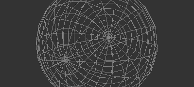 The sphere in wireframe mode.
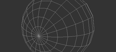 The front-facing polygons of the sphere.
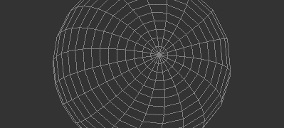 The back-facing polygons of the sphere.
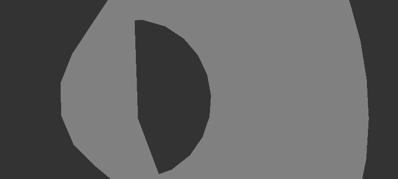 Open cylinder, with solid front-facing and back-facing polygons.
 The red cylinder with blending enabled.
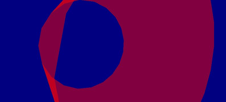 The cylinder with a dark blue erase color.
 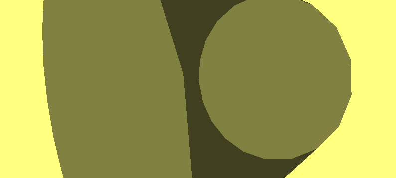 The cylinder with a setting of
 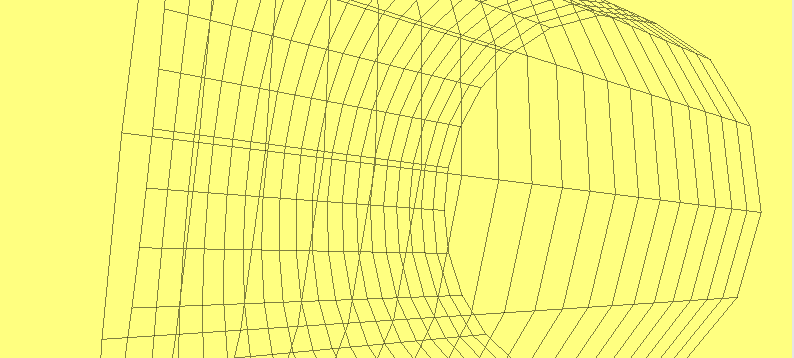 Antialiasing off
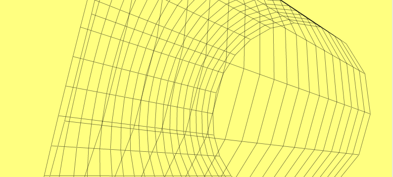 Antialiasing on