MIDI Control of VideoAudio Control of VideoJitter Tutorials
Tutorial 27: Using MSP Audio in a Jitter Matrix
This article is obsolete. With Apple's withdrawal of support for quicktime spigot~ is no longer available. However the jit.movie~ object duplicates its functionality, and the tutorial patch has been updated to demonstrate.
This tutorial shows how to copy an MSP audio signal into a Jitter matrix using an object called jit.poke~. Along the way, we'll investigate how to use the soundtrack from a movie in the MSP signal network using the sound output component attribute of the jit.movie object and a new MSP object called spigot~.
This tutorial assumes familiarity with routing MSP signals using send~ and receive~. It also uses a simple delay network using tapin~/tapout~ objects. Tutorial 4 and Tutorial 27 in the MSP manual cover these topics.
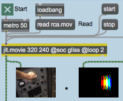
The jit.movie object at the top left of the tutorial patch reads a movie called rca.mov upon opening.
Our jit.movie objectStart the metro object at the top of the patch by clicking the toggle box. You will see an image in the lefthand jit.pwindow object below the jit.movie object. You won't see anything in the other jit.pwindow objects yet, nor will you hear any sound.
Our jit.movie object has two attributes set in its object box in addition to its dim attribute (320 by 240 cells). The loop attribute with a value of 2 tells the jit.movie object to loop the movie as a palindrome. Once the playback of the movie reaches the end, it will play backwards to the beginning of the file, rather than looping around to the beginning and playing forward (the default behavior, when the loop attribute is set to 1). If you watch the movie, you'll see that the arm manipulating the oscillator control moves up and then down again in an endless loop. The movie actually only contains footage of the arm moving upward, but the loop attribute we've used reverses the playback in the second half of the loop.
The Sound Output Component
The second attribute we've set in our jit.movie object sets the Sound Output Component (soc) for that instance of the jit.movie object. The name specified as an argument to the soc attribute (in this case gliss) specifies a new sound output component that MSP can use to acquire the soundtrack of the movie loaded into the jit.movie object. By default, the soc attribute is set to none, which routes the movie's audio output directly to the Sound Manager. A named soc attribute routes the audio to a spigot~ object with the same name as the component, allowing you to access the audio signal in MSP:
The spigot~ object
The spigot~ object in the upper-right hand corner of the tutorial patch has an argument (gliss) which matches the soc attribute of our jit.movie object. If a movie file loaded into that jit.movie object has a soundtrack (which the rca.mov file conveniently does), the audio from the movie is sent out as MSP signals from the spigot~. Note that the spigot~ object has two outlets, which correspond to the left and right audio channels of the movie soundtrack. Our rca.mov file has a monaural soundtrack, so we only need to use one of the outlets in our patch.
Important: The soc attribute of the jit.movie object allows you to create a separate sound output component for each jit.movie object in your patch. You can use as many spigot~ objects as you like, each with a unique name, to grab the audio from multiple movies. It's important to note, however, that you can only have one spigot~ object per sound output component, and each jit.movie object must have a unique soc attribute (unless, of course, the soc is set to none—System Sound can take the sound from as many movies as you wish). Once you have multiple movie audio tracks as MSP signals you can mix them as you please.
Start the dac~ object at the bottom of the patch by clicking the toggle box attached to it. You will see images appear in the remaining jit.pwindow objects and will see a signal level appear in the meter~ object attached to the spigot~. If you turn up the gain~ slider attached to the dac~, you should begin to hear sound out of whatever device you currently have selected as your MSP audio driver. For more information on how to set up your computer's audio system with MSP, consult the MSP tutorial Audio I/O - Audio input and output with MSP.Receiving the audio signal from the spigot~
The soundtrack from the rca.mov file is sent as an MSP signal from the spigot~ object into a two-tap delay line (generated by the tapin~ and tapout~ objects in the patch). The dry audio signal is sent to a send~ object with the name red attached to it; the two delay taps are sent to send~ objects named green and blue, respectively. The three audio signals are output by named receive~ objects and summed into the gain~ object at the bottom of the patch, allowing you to hear all of them at once.
Adjust the delay times using the number box objects labeled Delay times (green/blue) attached to the tapout~ objects. You can adjust the delays up to a maximum length of 1000 milliseconds (the maximum delay time allocated by our tapin~ object).
Poke~ing Around
The righthand jit.pwindow object at the top of the tutorial patch shows the output of a jit.matrix named scope, which also gets bang messages from the metro object at the top of the patch:
The output of the scopejit.matrix
The scope Jitter matrix is generated by three jit.poke~ objects at the right of the tutorial patch, which write MSP audio signals into cells in the matrix. These cells, when displayed in the jit.pwindow object, portray an oscilloscope view of the movie soundtrack, with the dry and two delayed signals appearing as the colors red, green, and blue, respectively.
The three jit.poke~ objects, writing into the scope matrix
The three similar regions at the right of the screen use the jit.poke~ object to write MSP signal data into our scope matrix. The jit.poke~ object takes three arguments: the name of the Jitter matrix to write into, the number of dim inlets to use, and the plane of the destination matrix to write numbers to. All three jit.poke~ objects in our patch write into the matrix scope. Since scope is a 2-dimensional matrix, we need 2 inlets to specify where to write the data (one inlet for the column and one inlet for the row). The three objects differ in that they each write to a different plane of the scope matrix.
The first inlet of the jit.poke~ object provides the value to write into the matrix cell specified by the other two inlets, which take signals to specify the cell location. We use a sig~ object with a value of 1 to write a constant value into our current position in the scope matrix. The value of 1 gets interpreted as 255 when writing into a matrix containing char data (which is what we're doing in this case).
The other two inlets in our jit.poke~ objects determine where in the output matrix they should write data (this set of coordinates defines the write pointer for the object—you could think of this as the location of the record head, only with two dimensions instead of one). The rightmost inlet receives the audio signal from our named receive~ objects and sets the vertical (dim 1) coordinate of the write pointer to correspond to the amplitude of the signal. The *~ and +~ objects in the patch scale the output of the audio signal from between -1 and 1 (the typical range for an audio signal) to between 0 and 239 (the range of the vertical dimension of our output matrix).
Sync or Swim
The middle inlet to our jit.poke~ object receives a sync signal that specifies where along the horizontal axis of the matrix we write the current amplitude from the audio signal. This signal is unrelated to the audio data coming from the movie—you could think of it as the horizontal refresh rate of the virtual oscilloscope we've made in this patch. The sync signal is generated by a phasor~ object in the Scope_setup subpatch:
Generating the horizontal sync signal for our jit.poke~ objects
Our phasor~ object generates a repeating ramp signal from 0 to (nearly) 1. The *~ below it rescales this signal to generate values appropriate to the width of our matrix (0 to 319). This signal is then passed to a send~ object with the name h_sync, which forwards the signal to receive~ objects connected to the middle inlets of our jit.poke~ objects. The frequency of the phasor~ (specified by the number box connected to its first inlet) determines the rate at which our jit.poke~ objects scan from the left to right through the matrix.
Try changing the frequency of the phasor~ by changing the number box labeled Horizontal scan rate (Hz). Notice how at higher frequencies you can see the waveform generated by the movie audio in more detail. If you set the rate to a negative value, the matrix will be written backwards (i.e. from right to left).
The dry audio signal and the two delayed outputs are visualized as the three visible planes of our scope matrix (1, 2, and 3, or red, green, and blue). When the cells written by the jit.poke~ objects overlap, different color combinations will appear in the output matrix.
Now that we understand how the matrix is being written, we need to look into how the matrix clears itself every time a horizontal scan is completed. The relevant parts of the patch are shown below:
Detect when the horizontal sync resets and clear the matrix
The change~ object outputs a value of 1 when the ramp generated by the phasor~ object is on the increase. When the phasor~ snaps back to 0 at the end of the ramp, change~ will briefly output a value of -1. The ==~ operator, which outputs a 1 when the change~ object
does, will output a 0 at that point. When the phasor~ begins to ramp again, the ==~ object
will output a 1, triggering a bang from the edge~ object (which detects a zero to non-zero transition in the last signal vector). The bang is then sent to a receive object named reset, which triggers a clear message to the jit.matrix object. As a result, our scope matrix is cleared every time the phasor~ restarts its ramp.
Putting it all Together
Our two Jitter matrices (the image from the jit.movie object and the oscilloscope drawn by our jit.poke~ objects) are composited into a final matrix by the jit.op object:
Compositing the two matrices using jit.op
The op attribute we've specified initially for our jit.op object is *. As a result, our composite is made from the multiplication of the two matrices. Since most of the cells in our scope matrix are 0 (black), you only see the movie image appear in those cells and planes where the jit.poke~ objects have traced the waveform.
Change the op attribute of the jit.op object by clicking on some of the message boxes attached to the prepend object to the right of the jit.pwindow showing the scope matrix. Notice how the different arithmetic operators change the compositing operation of the two matrices.
Summary
The soc attribute of the jit.movie object lets you define a named Sound Output Component. The spigot~ object lets you access the soundtrack of a movie as an MSP signal by giving it an argument that matches the soc attribute of the jit.movie object playing the movie.
You can use the jit.poke~ object to write data from MSP signals into a named Jitter matrix. The jit.poke~ object takes arguments in the form of the name of the matrix to write to, the number of inlets with which to specify cell coordinates, and the plane to write to in the matrix. The first inlet of jit.poke~ takes the value to be written into the matrix. Subsequent inlets take MSP signals that specify the cell location in the matrix in which data should be written.
Report signal directionAudio output and on/offDetect logical signal transitionsThe Jitter Matrix!Apply binary or unary operatorsWrite an audio signal into a matrixIn-Patcher WindowPlay or edit a movieSawtooth wave generatorRoute QT audio into MSPInput to a delay filterOutput from a delay line
 Our
Our 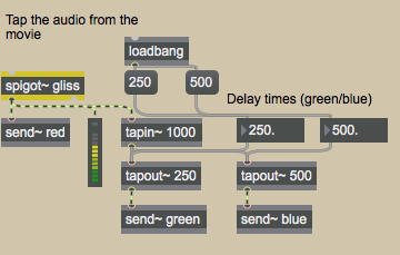 The
The 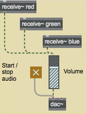 Receiving the audio signal from the
 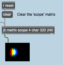 The output of the
 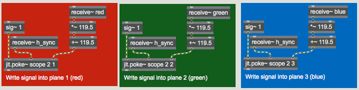 The three
 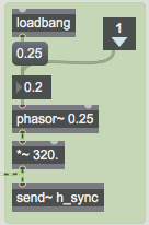 Generating the horizontal sync signal for our
 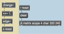 Detect when the horizontal sync resets and clear the matrix
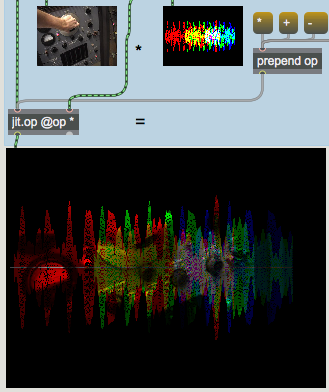 Compositing the two matrices using